Electronics Rework Heaters
Repair technicians demand accurate repeatable results from their hot air solder rework equipment. At the heart of this functionality is the heating and control system that warms the board and melts the solder. Accurate temperature control reduces thermal stress protecting the board and surrounding components. Temperature precision also means durability due to strong and clean solder joints. Whether reworking by hand or an automated solution, reliable heating elements with consistent temperature-control are crucial for rework station success.
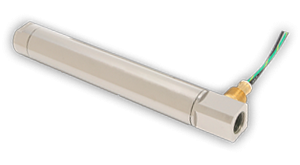
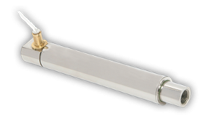
Two different air heater styles manufactured by Tutco-Farnam for use in electronics rework stations.
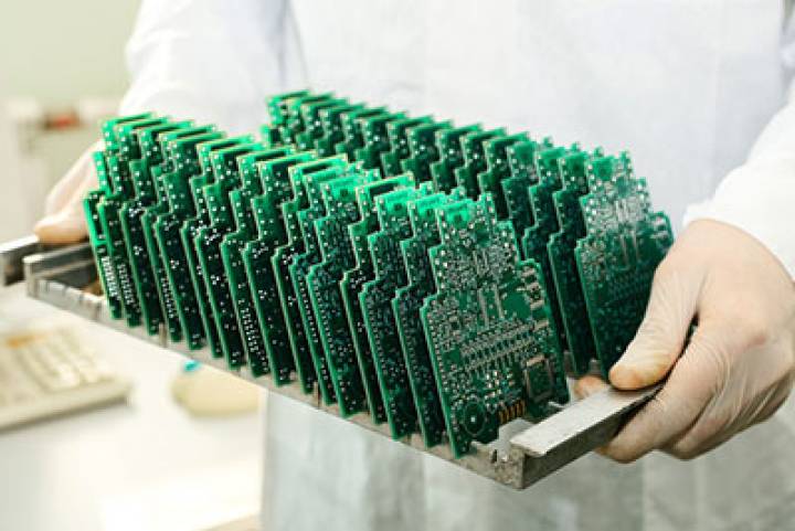
Heaters are needed to melt solder for removing components, cleaning up older solder, and the reflowing new solder. The components being reworked are almost always SMDs (surface-mount devices). As components get smaller and packed closer together the need for precision temperature control becomes increasingly more important.
There are five steps to electronics rework:
- remove a damaged or misaligned component
- clean pads and any components that will be reused
- dress pads
- position component
- reflow solder
Solder rework stations typically have two heaters. A bottom heating element preheats the board and components from below. This takes place during a preheat stage, helping to reduce thermal shock and gently removing moisture. A top heater does the heavy lifting of melting solder in a specific part of the board.
Solder Reflow Profile
A solder profile (also called a thermal or reflow profile) provides the accurate consistency needed to properly preheat the board, melt fresh solder and safely cool the board back to room temperature. Hot-air rework heaters execute the demands of a thermal profile with precision resulting in strong clean solder joints. When rework heating elements fail to deliver with consistency there is a risk of immediate as well as longer-term (product in the field) damage.
 BGAs (Ball Grid Arrays) in particular are prone to disaster when reworked without the aid of a profile and the precision of highly engineered thermal controls. BGA solder pads are on the bottom of the chip allowing it to have many connections with the board. Being on the bottom, these pads are not directly accessible after reflow. If tests reveal any failed connections or unwanted solder bridging between pads they will need to be completely removed. BGAs are also hygroscopic. If they are sitting around in a damp environment and you ramp up to peak temperature too quickly, they are going to 'popcorn' and destroy that chip. The damage is due to the moisture in the chip becoming steam and forcing it's way out.
There are four stages to reflow that can be viewed on a temperature/time graph as a reflow profile:
- Preheat: We want the heat to safely penetrate the board, dry components that may have taken on moisture, and expedite solder paste outgassing (removing flux volatiles). The preheat ramp is a slope measuring temperature over time. Typical rates are between .5°C/sec and 2°C/sec. Rates will be slower when temperature-sensitive components are in the vicinity.
- Soak (Pre-reflow): Preheat takes us to the soak stage where the copper filled board soaks up heat. Surface oxide on leads, pads, and within the solder itself needs to be removed to allow solid reflow bonding. The chemistry of flux within the solder is designed to remove oxides from metal surfaces and then to protect the surfaces so they don't re-oxidize. Different flux technologies do this differently. The removal of oxides happens during this stage. Temperature is held fairly steady to allow the board and components to have a uniform starting temperature before we begin our ramp to reflow. As we ramp up to peak temperature we are careful not to reflow too fast and thermally shock the piece being worked.
- Reflow: The reflow stage is when the solder melts. This will be a temperature above the melting point of the solder but not to exceed a specified peak temperature.
- Cooling: The cooling stage is also a controlled stage. Cooling should be fast enough to achieve a fine grain structure within the solder but not so rapid as to cause thermal damage such as cracking. Heaters are used to slow down and control the cooling process.
The ideal conditions for each stage can be measured and saved as a rework 'profile'. Each stage of a profile has it's own purpose and as such will have characteristics that are distinctly different from the other three stages. It is critically important that heaters and controls respond precisely and consistently to the conditions specified by the profile.
Engineered Heating Solutions
Circuit board rework equipment needs to provide reliable repeatable results. Heating elements are fundamentally important to that endeavor. Tutco-Farnam has decades of experience designing and building custom heaters for OEMs. Chances are we have built something similar to the solution you seek. We can build a custom solution or configure a standard product. Contact us today to see what Tutco-Farnam can do for you.